


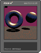
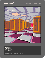
I felt like ray marching a signed distance field in PICO-8.
(Don't ask me why..).
 10 comments
Pseudo 3D racing games are fun. They have a cool retro arcade feel, with a good sense of speed, and can run on low end hardware. Plus they're pretty straightforward to implement - and satisfying.
There are lots of different ways to write a pseudo 3D racer, but I'm just going to show you how I do it.
This is the method I used for Loose Gravel, and can render corners, hills, tunnels and background sprites in an efficient manner. It doesn't need any 3D drawing hardware, just basic 2D rectangles, lines, scaled sprites and rectangular clip regions. Pico-8 can do all of these.
Defining the road
The road is made out of "corners" (for our purposes we will call straight bits "corners" as well). Corners need to curve in the direction the road turns, so we will simulate this by building them out of smaller straight "segments".
We can define the track as an array of these corners.
road={
 {ct=10,tu=0},
 {ct=6,tu=-1},
 {ct=8,tu=0},
 {ct=4,tu=1.5},
 {ct=10,tu=0.2},
 {ct=4,tu=0},
 {ct=5,tu=-1},
} |
Each corner has a segment count "ct" and a value indicating how much the direction turns between each segment "tu".
So tu=0 creates a straight piece, tu=1 will turn to the right, -1 left etc.
For simplicity we'll ignore hills and valleys for now.
Drawing the road
We will draw the road by walking a 3D "cursor" along it and drawing the road at each point.
We'll define the cursor like this:
local x,y,z=0,1,1 |
We will start drawing the road slightly in front (z=1) and below (y=1) the camera position.
Note: I use x=right, y=down, z=into the screen as my coordinate system. I find this easiest to work with, having x and y in the same direction as on the screen and keeping z coordinates positive.
The direction of the road is another 3D vector:
local xd,yd,zd=0,0,1 |
So initially the road will point straight forward (zd=1).
The direction will be added to the cursor's 3D position to move from the current segment to the start of the next. To keep the maths simple we're using segments of length 1.
We also need to track which corner and segment we are drawing:
local cnr,seg=1,1 |
The main drawing loop will draw 30 segments of the road from the starting position, as follows:
- Draw the road at the current position
- Move to the next position in 3D space
- Adjust the direction based on how the road turns
- Advance to the next segment (and corner if applicable)
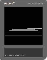
Putting this together, gives us something like this:
Click "code" up above to view the code.
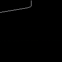
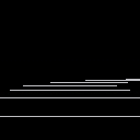
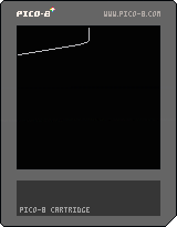
It's just a static boring line for now, but the basic logic is there. I was pretty vague about what "draw the road" means so we're just drawing a line to the x and z coordinates of the "cursor" for now.
We can see that the road goes straight for a bit then turns to the left as it moves down the screen.
We're "adjusting the direction" by adding the turn amount for the current corner to the X coordinate of our direction vector:
xd+=road[cnr].tu |
which means we're actually skewing the road rather than rotating it. This is part of the "pseudo" in our pseudo 3D - the difference is if we were using proper rotation the road would eventually turn around and start coming back towards us - if it turned far enough - whereas with skewing it just keeps stretching out more and more horizontally.
Although less realistic, skewing is much simpler to implement, and means that the road will always face away from the camera, which makes drawing things in the right order a lot simpler. And as long as the corners aren't too sharp it's an acceptable approximation.
Making it 3D
The key making this 3D is called perspective projection.
This converts a 3D coordinate into a 2D screen coordinate. I won't bore you with the mathematics - there are plenty of other places you can find this information if you really want to.
The important thing is the formula, which is:
- px=x*64/z+64
- py=y*64/z+64
This gives a 90 degree field of view (FOV). Replacing the 64 in 64/z with a smaller value would give a wider FOV, or a larger value would give a narrower FOV. We'll stick with 64 however. The +64 moves everything into the center of the screen.
64/z is also a useful value to keep, because it is the scale factor for anything drawn at that position, such as scaled sprites, or the road width. So the project function will return this too:
function project(x,y,z) local scale=64/z return x*scale+64,y*scale+64,scale end |
With this we can replace the line drawing code in the main loop:
-- project local px,py,scale=project(x,y,z) -- draw road local width=3*scale line(px-width,py,px+width,py) |
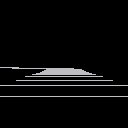
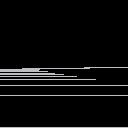
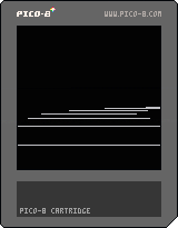
The projection allows us to draw a horizontal line 6 units wide, scaled appropriately for the 3D position.
This produces something a little more like looking down a road.
Adding movement
Right now the road is static, because it is always drawn from the same position.
To get the sensation of movement we need to simulate a camera moving down the road, and draw it from the camera's position.
So we'll declare the camera:
camcnr,camseg=1,1 |
And change "cursor" in the _draw() function to start from the camera position:
local cnr,seg=camcnr,camseg |
We can use the same logic to advance the camera to the next segment as we do for the "cursor" when drawing, by moving it out into a function:
function advance(cnr,seg) seg+=1 if seg>road[cnr].ct then seg=1 cnr+=1 if(cnr>#road)cnr=1 end return cnr,seg end |
This advances to the next segment in the corner, and if necessary the next corner in the road, looping around to the first corner if required.
Then we call it from the _draw() function:
-- advance along road cnr,seg=advance(cnr,seg) |
And use it to advance the camera in _update():
function _update() camcnr,camseg=advance(camcnr,camseg) end |
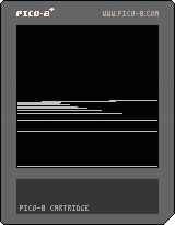
Putting it together we get:
Which sort-of looks like movement, but isn't totally convincing.
The camera is moving one full segment per rendered frame, which means the segment lines are rendered at the same distance each time.
We need to move less than a full segment per rendered frame, which means we need to track the camera position relative to the current segment:
camx,camy,camz=0,0,0 |
Now we can advance the camera by less than a full segment length:
function _update() camz+=0.1 if camz>1 then camz-=1 camcnr,camseg=advance(camcnr,camseg) end end |
Inside _draw() we start drawing relative to the camera position, by subtracting the camera coordinates from the starting coordinates.
local x,y,z=-camx,-camy+1,-camz+1 |
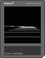
With these changes the forward movement feels more convincing:
But now cornering feels janky.
This is because the camera is always aligned exactly with the segment it is on, so when it moves to the next segment it snaps sharply.
To counter this we need to turn the camera smoothly towards the next segment's angle as it progresses down the current segment. We can compute this angle in _draw() as:
local camang=camz*road[camcnr].tu |
Then subtract it from the initial cursor direction:
local xd,yd,zd=-camang,0,1 |
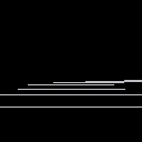
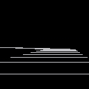
This gives some improvement:
It's still not 100% though - there's still some horizontal juddering.
This can be a little tricky to understand the cause of.
The gist of it is that by turning the camera, we're skewing the first segment will be rendered. But when we calculate the cursor position relative to the camera, we're using the un-skewed camera offset. So when we draw the road forward again, the part that should pass through the camera point will actually be skewed left or right of it. This makes the camera appear to diverge from the path of the road as it moves towards the end of the segment. It then snaps back into the center when it progresses to the next segment.
To fix this issue we need to first skew the camera position in the "cursor" direction, then calculate the cursor position relative to the skewed camera position.
We'll start by creating a basic skew function:
function skew(x,y,z,xd,yd) return x+z*xd,y+z*yd,z end |
Essentially we're skewing the Z axis from (0,0,1) to (xd,yd,1).
We'll need to re-order the "cursor" setup code in _draw(), so that the direction is calculated first.
I.e. move this bit in front of the initial x,y,z calculation:
-- direction local camang=camz*road[camcnr].tu local xd,yd,zd=-camang,0,1 |
Then we can calculate the skewed camera position:
local cx,cy,cz=skew(camx,camy,camz,xd,yd) |
And calculate the initial "cursor" position relative to the skewed camera:
local x,y,z=-cx,-cy+1,-cz+1 |
This finally gives us nice smooth camera movement:
This is the core road drawing algorithm for a pseudo 3D racer.
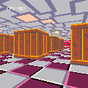
The last step is to simply clean up the rendering so it's not just white lines on black.
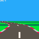
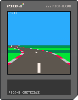
With a little bit of work we can turn it into something like this:
I won't go into too much detail here - you can refer to the cartridge code for specifics - I'll just touch on a few basic points.
To draw the road we need to render a trapezium (also known as a trapezoid). Essentially we're joining the horizontal lines together and filling them in. Pico-8 doesn't have a built in trapezium drawing function, but we can roll our own by stacking 1-pixel high rectangles.
We use alternating colours to communicate speed, which is a common technique in pseudo 3D racers. The easiest way to do this is to track how many segments we are along the road as a whole. Then we can use the modulo operator (%) to determine whether we are on an odd or even segment, or every 6th segment etc, and use that to select a colour.
We pre-calculate this (as "sumct") for each corner of the road in an _init() function. This makes it easy to calculate for any corner and segment:
function getsumct(cnr,seg) return road[cnr].sumct+seg-1 end |
We use this to alternate the ground colour every 3 segments.
We don't have to stop at just drawing a plain gray road. The projected positions, trapezium drawing routine and colour alternation give us the tools we need to draw other road features. So we've drawn road markings as a thin trapezium every 4 segments in the middle of the road, and shoulder barrier things on the sides of the road, alternating red and white every other segment.
With the basic rendering in place this is a good time to tweak the parameters to get the right look and feel. The following adjustments were made:
- Moved the road start point to (0,2,2) in front of the camera
- Reduced the corner "tu" values, as the corners were too sharp
- Increased the movement speed from 0.1 to 0.3
Next steps
This feels like a good place to leave the first tutorial.
In part 2 we'll cover drawing roadside objects (and overhead objects) using scaled sprites.
I just noticed the += shorthand doesn't work the way I expected with comma separated values.
For example:
x,y,z=1,2,3 x,y,z+=10,20,30 |
Sets x to 11 as expected, but y and z are set to 20 and 30 respectively, rather than 22 and 33.
Should the last line be equivalent to:
x+=10 y+=20 z+=30 |
?
Or is there some reason I'm missing?
I'm sure this has been done dozens of times already, but I thought it would be fun to give it a go.
So here's a simple Wolfenstein 3D style ray-caster.
There's no game-play at all, you can just move around.
You can edit the level in the pico8 map editor (make sure it is always enclosed, otherwise you'll get an infinite loop - rays only terminate when they hit a wall).
Update: Cleaned up & optimised code. Added textured ceiling and floor.
|
40 
|
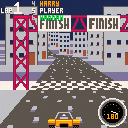
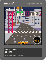
This is Loose Gravel! A pseudo-3d racer that started as a proof of concept, and gradually grew into something of a game.
If you're curious, you can view the progress here.
Pretty self explanatory. Choose a course and try to overtake the other cars in 3 laps to win.
Courses are randomly generated but have their own unique parameters and feel.
I was planning to add a tournament mode (and some more tracks), but I ran out of cart space (so that means it's finished! :) )
Tip: If you tap the up arrow you will keep accelerating until you hit something or drive off the road. You don't need to hold it down.
Enjoy.
-Mot
Update: Replace scaled map routine with tline version
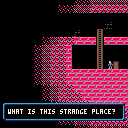
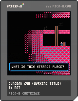
I wanted to share a little work-in-progress I've been tinkering on.
Dungeon guy doesn't know what he's searching for. Maybe treasure? Maybe a way out? Maybe dungeon girl?
All he knows is to keep searching.
Levels are randomly generated and get progressively larger.
The only objective so far is to find the key and the exit door.